Software
This page describes the packets and software used for tooltron. We will cover both the board firmware and the server software. For the most up to date documentation and how the code works, refer to the Doxygen documentation or the comments within the code.
Error Codes
| Fast red light blinking on Toolbox power-up | EEPROM ID cannot be read |
| Fast alternating red and yellow lights on Toolbox | Mechanical switch is on but Tooltron has not given power to the tool |
Configuring tools
To set up a toolbox (or change timeouts) the code must be modified. Open toolbox/main.c and look at the #define config options near the top of the file. You must recompile the code and reprogram the board that you wish to configure for the changes to take effect.
tool ID
The tool IDs are written to the EEPROM for permanent storage. This cannot be 2, 1 or 0 and does not need to be the same as the keypad which is pressed. The key which corresponds to a tool can be changed separately (see server config below). The tool ID must be an integer value.
Timeouts
There are three timeouts that can be configured. They are TWAIT, TWARN, and TMAX. They are all located in main.c. All units for the timeouts are in minutes.
TWAIT defines the amount of time to wait from when a tool turn on command has been sent from the server until the tool will return back to the idle state. This is the window of time that the user can turn power onto the tool and transition it to the ON state.
TWARN defines the amount of time from when the tool enters the ON state until it begins warning the user that their time is about to expire. It is during this time that the time can be extended by the user.
TMAX defines the amount of time from when the tool enters the WARN state until it turns off the tool due to time expiration (unless the tool is running, in which case power will not be shut off until the current draw is removed).
Packet Format
The packet format is designed to allow simple parsing using the parse_packet code stored in the bootloader.
The format is as follows:
| Start Delimitor | SRC | DEST | CMD | PLEN | Payload | Check Sum |
- The start Delimitor is always '^'
- SRC is the ID of the sender
- DEST is the ID of the intended recipient
- CMD is a byte identifying the command (similar to the "type" of packet)
- PLEN is the length of the payload (>= 0)
- Payload is a sequence of exactly PLEN bytes (may be 0)
- Check Sum is a byte xor'ed of every byte except the start delimitor
NOTE Should the PLEN become corrupted, the checksum may not be checked correctly. In practice this has not been observed but is possible
SRC and DEST can be any number from 0-255. Here are the reserved values:
| Address | User |
| 0 | Global |
| 1 | Server |
| 2 | Card Box |
Tool IDs start at 11.
Valid commands are:
| Character | Name | Description |
| a | Ack | Acknowledgement |
| n | Nack | Non-Acknowledgement |
| x | transaction | A keypress and card-id pair (variable length data) from the cardbox |
| q | grant | Access to the tool specified in transaction granted |
| f | deny | Access denied |
| t | Timeout | A timeout has occurred |
| r | Reset | Signals a tool to reset |
| b | Boot | Signals that a tool is in bootloader mode and ready to receive a new program |
| p | Program Mode | Signals that the server is ready to send a new program to the bootloader |
| d | Program Data | signifies a packet of data making up the program code |
| g | Ping | Simply request an ACK if the DEST is alive and listening |
| Character | Name | Description | Reason |
| o | On | Turn on power to tool | Server now sends grant message to allow the tool to turn on |
| s | Send Key | A response with a keypress in the payload (should be from the keypad) | New cardbox |
| k | Get Key | A request for a keypress (should be to the keypad) | New cardbox |
Checksums are the XOR of all the bytes excluding the start delimitor.
Cardbox Firmware
The cardbox contains the keypad and is connected to the server. To board will receive a Get Key request from the server. The board then illuminates the yellow light and waits for the user to press a button on the keypad. Should the user not press a key within the timeout time, a Timeout packet is returned to the server and the red light is shown. Otherwise, the last key pressed is sent to the server. The cardbox will then waits again. If an Ack is received, the green light is displayed indicating that the user has the permissions required to run the tool. Should the server return a Nack, the cardbox displays the red light indicating that the user does not have the correct permissions.
Toolbox Firmware
The toolbox interfaces the server to the tool. It simply sits in a loop waiting for data to come in. Should the address of the packet match, the tool will parse the packet. Otherwise it will be discarded. Once the packet is parsed, the toolboard checks for a On command. Should that be valid, the toolboard initiates the timers and waits for button presses. At this time the yellow light is on. If a red button is pressed the timer is disabled and the toolboard returns to waiting for packets. A red light is displayed briefly indicating ot the user that the tool is disabled. If the green button is pressed, the toolboard turns on the relay, giving power to the tool. The green light is now illuminated and the yellow light turned off.
While the tool is running the toolboard monitors the AC line. Should it detect that the tool is running, it will not turn off power to the tool for safety reasons. The timers will count down on the tool after the green button is pressed. Should the timer expire, the yellow light will blink, indicating to the user that the tool will turn off as soon as the tool is powered down. A green button will increase the time on the timer. If the tool is turned off while the timer still has power, it can be turned on again though the timer will not be refreshed. Finally, the timer cannot be extended unless the yellow light is blinking. Should the time expire and the user turn off the tool, the user must return to the cardbox and re-request the tool.
Note in the firmware that the buttons are labelled black and red. The green button is also the black button. This is a holdover from the original tooltron system that used black buttons.
Server Software
The server software sits in a loop waiting for input from the USB card reader. When a card is swiped, the server software parses out the Carnegie Mellon card ID number and stores that. It then sends the Get Key command to the cardbox. Once the key is received, the server queries the members database, passing in the card number and the requested tool number. Should the cardbox not return a tool, the request is discarded. If the user is allowed on the tool, the server sends an Ack to both the cardbox and to the toolboard to turn it on. If the user is not allowed the server sends a Nack to the cardbox.
Note that the server is not setup to handle concurrent requests. Users should only swipe one at a time.
Payment Status Checks
Before granting access, tooltron checks the database to see if the member has paid recently:
| Start Date | End Date | Semester | Payment |
| Aug 20 | Dec 31 | fall | must have paid after aug 20 of current year |
| Jan 1 | May 20 | spring | must have paid full year after aug 20 or one semester after jan 1 |
| May 21 | Aug 19 | summer | same as spring |
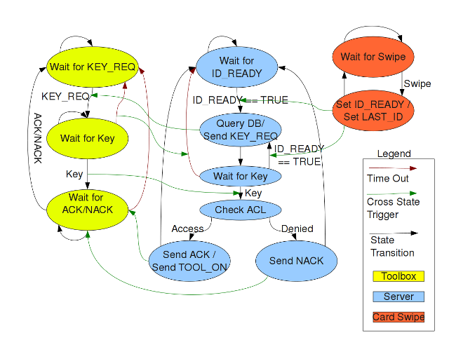
State Transition Diagram
This is a diagram of the three state machines between the cardbox, server, and card reader.
![]()
CiviCRM
We simply read the civicrm database through mysql and parse the information needed. We use custom fields to store each users tool permissions which are queried.
The database is whitelisted. To grant access:
- ssh in to roboclub8
- run 'mysql -u tooltron -p'
- enter the password (t..., the old one)
- At the mysql prompt type: GRANT ALL ON civicrm.* TO tooltron@'_ip_' IDENTIFIED BY '_t..._';
Where ip is the ip of the system you want to add and t... is the t password
Network Bootloading
Order of events- Server sends a reset packet to a specific tool
- Tool reboots
- Tool sends a boot packet to the server
- Server responds with the program packet to tell the tool to prepare to receive a program, packet also contains number of bytes that the program will be
- Tool acks packet to the server
- Sever sends MAX_PACKET_SIZE in Data Packets
- Tool writes each packet to flash after checksum verification, acks packet
- Repeat until upto the final program size
- Tool jumps to new code and begins execution
If there is ever an interruption of the stream, both the Tool and the Server must reset. The tool discard and program data received. The server should resend to the program, the tool shall attempt to be reprogrammed until successfully reprogrammed.
The bootloader is only on the Toolboxes. Since the ATTiny2313 has self programming memory (allowing it to be programmed) but no bootloader section, we had to do some trickery to make the bootloader work. The bootloader is located in the upper half of memory.